Friday, May 20, 2016

Final Project: Calculating surface flow models using UAS imagery

Introduction

The lower Chippewa River (LCR) has been a point of investigation for students and faculty of the Geography Department at the University of Wisconsin – Eau Claire (UWEC). The close proximity to campus as well as it’s interesting characteristics have lead to many student-faculty research projects. The summer of 2015 I part took in research investigation downstream finning of clast sizes on the LCR. The LCR contains abrupt changes in channel planform morphology. Most notable is an anabranching reach in the middle of the study area. Both upstream and downstream from this reach the river exhibits a single meandering channel planform. Sedimentology changes within the channel are possibly related to the anabranching reach. Where the channels of the anabranching meet into one channel again there is a large point bar with large clast sizes on it. This point bar is formed by complex hydrology that The purpose of this project is to use the UAS as a tool to investigate the bars properties. This project specifically looks at surface flow models to help delineate features on the bar. Also, this is the first mission flown of the point bar and will be used as a stepping stone for further investigating the bar over time.

Figure 1. The Blue square represents the UWEC campus. The Red square represents Birthday Point bar at the end of the anabraching reach. 
Study Area

This point bar, which will be referred to as Birthday Point, is at the end of the anabranching reach – a very active portion of the river. This Part of the river has changed over the years as shown by the imagery below. The bar was formed after a flood cut through a chute seen in the fist image (1938). From 1985 to the today there as been dramatic change in the point bar. UAS imagery will allow for more detailed changes to be documented in the year to come.

Methods 

Data was collected with the DJI Phantom with a built in camera (12 megapixels). Data collection started around 9 am to insure calmer winds on the exposed bar. Five ground control points (GCPs) were set up around the bar. The coordinates were collected using a dual frequency GPS. Two flights were flown, one containing just the point bar and the other imaged a part of the point bar and opposite south-west bank. Imaging the opposite bank of the point bar was done to hopefully monitor changes in both sides of the river over time. Flight one lasted for ten minutes as well as flight two and were taken at an elevation of 40 ft.

Data was then brought into Pix4D for processing. GCP data tables were massaged to use for tying down the imagery. However, complications arose with using the GCP’s in the Tie Point Manager and after trouble shooting they were left out for further processing. When the processing was completed the Mosaic and DSM data was brought into ArcMap. A mask was created to clip out any unwanted data such as the trees and the water that would skew the flow model (FIGURE). With the clipped DSM the tiff was brought into QGIS. QGIS was used to model the surface flow using the Geographical Resources Analysis Support System (GRASS) ‘terra.flow’. This yielded a graphical representation of the flow on the point bar. This was chosen over the ArcGIS ESRI surface flow model because the QGIS model provided a more graphical representation of the flow.

Results

The output imagery illustrates the accumulated flow on the point bar. There are distinct channels of surface flow heading in a western direction.  
Figure 3: Above is a final map of the terra.flow GRASS model. There appears to be three main channels of flow. 
Figure 4: Zoomed in area go the graphic (eastern section). The darker areas represent the areas of greater flow accumulation. 


Discussion

The output imagery illustrates the accumulated flow on the point bar. There are distinct paths in which the water flows, possibly representing the formation of the bar or complex flow patterns during high floods. While DSM data allows for the visualization of the surface – applications such as calculating the surface flow can enhance the comprehension of the topography of this complex bar.

While we didn’t use GCP’s for this data the model still works as the flow is calculated using pixel values. However, the GCP’s will be used for future research in comparing present and future conditions of the bar. For future research I would recommend cutting out as much of the trees as possible unless the flights are flown to map scroll bars at a greater height. One reason the data may be wonky is because of the amount of water captured in the imagery. UAS and bodies of flowing water don’t mix and can distort the data. As shown in the DSM or even the mosaic data there are lines of distortion that may be attributed to the camera interacting with the water as the lines show stronger distortion in the western portion of the bar.


Figure 4: In the eastern portion of the imagery there are clear lines of error that appear to intensify as they move east. 
Conclusion


This project is the first step of, hopefully, continuous imagery of this dynamic bar. In the future it is recommended to use the GEMS platform and software and Thermal camera to collect imagery. With the GEMs software near infrared bands could help detect moisture levels on the bar. Thermal Imagery could do this as well. Further investigation of why the GCP’s were not working is required if this imagery is to be used to compare to future missions. Calculating the surface flow models was useful to help delineate the paths of water as well as identify complex features on the bar.

Monday, May 2, 2016

Volumetrics Lab

Introduction:

Producing accurate volume measurements of materials is important in many applications today. For example, inventory and management of stockpiles and pits of mining companies. It is important for companies to keep track of stockpile material inventory. Traditional methods of gathering volume information can be risky as piles can be larger, difficult to traverse, and non-uniform in shape making calculation difficult and can take a long time to get results. Three major areas of error exist in calculating stockpile volume according to Firmatek, an inventory management company: “poorly defined base”, “insufficient data on top of the stockpile”, and “including extra material”. Today, “fly-over” methods using photogrammetry collected by Unmanned Aerial Systems (UAS) can be used for high accuracy and speedy results.

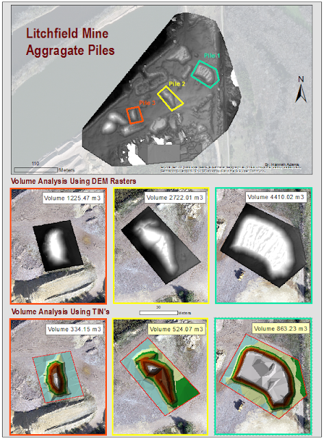
Volumetric analysis is used to find volume in different programs depending on the type of data. For instance, DEM and TIN files can be used to calculate volume in ArcMap and photogrammetric images can be processed in Pix4D. Accurate volume measurements are necessary in today’s world as we move towards responsible tracking of material. In this lab volumes of stockpiles at the Litchfield mine will be calculated. This lab will compare the advantages and disadvantages of three methods used to calculate volume. 

Methods:

Calculating Volume with DEM in ArcMap:

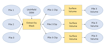
With this method a DEM of the study area was imported into ArcMap. From here, individual aggregate piles were chosen and clipped by making polygons to be used for the Extract by Mask tool. After each pile was clipped (Fig. 1) the identify tool was used to get a sense of elevation at the base of the pile. This information is crucial to calculate volume but in this case we have to estimate the average height around each pile. Then the Surface Volume tool (Fig. 2) was used and the to enter the estimated base elevation into the Plane Height field to calculate the volume in the raster above that elevation. This information was then added to an output text file. This can all be seen in the workflow below (Fig. 3).
Fig. 1: To the left is the Litchfield Mine DEM raster with the corresponding polygons
 used in the Extract by mask tool. To the right are the out put clipped rasters. 

Fig. 2: Here is the Surface Volume tool window. When using this tool make sure the
Reference Plane is set to "ABOVE" when calculating for a pile.

Fig. 3: Here is the workflow for calculating the volume of piles on the Litchfield Mine Site.

Calculating Volume with TIN in ArcMap:

For this method the raster clips produced in the previous method were used and converted into TINs using the Raster to TIN tool in ArcMap. After this was done a polygon was created to outline the "base" of the pile (Fig. 4). Next, the Add Surface Information tool was used to assign a Z_MEAN value in the attribute table of the polygon. This is done by entering the ploygon as the Input Feature Class and the Tin as the Input Surface . Now the volume can be calculated using the Polygon Volume tool. The Input Feature Class is the polygon but there is an additional field, Height Field, where the Z_MEAN field is entered (Fig. 5). After this the Volume value for the pile is attatched in the polygon's attribute table. Repeat these steps for each pile you wish to calculate the volume using a TIN (Fig. 6).

Figure 4: On the left is the TIN for pile two after the Raster to TIN tool was used.
The right image illustrates the polygon that was made to represent the base of the pile.

Figure 5. The final step for calculating the volume of an aggregate TIN pile.

Figure 6: A workflow for calculating the volume of TIN's. 

Calculating Volume with Pix4D:

To calculate a volume measurement in Pix4D right click objects in the rayCloud tab and select new volume. From here, click at the base of a pile to add a vertices and complete an outline of the base by right clicking. On the left hand side of the screen a window will appear, click the "update measurements" button to calculate the volume. After the Volume is calculate the pile will turn red as shown in Figure 7.


Results:


Conclusion:

Monday, April 11, 2016

Project Proposal: Drainage Flow model of the Litchfield Mine Site

Intorduction 

This research project will focus on the development of a drainage flow model for a mine site. Calculating hydrologic characteristics at a mine site are important when considering environmental health and mine management. Improper management of stock piles may lead to erosion of aggregate piles due to storm runoff.  The main objective is to observe is ArcGIS will be able to calculate a detailed drainage model using UAS imagery. Hydrology tools in ArcMap will be used to model the flow of water across the surface. Three tools that will be used are Fill, Flow direction, and Watershed. Results of this project will add to the conversation of high resolution hydrology flow models extracted from UAS imagery.
                                                                          
Study Area

The Litchfield Mine site will be used for this project. The Mine site contains multiple stock piles and a holding pool located next to the Chippewa River (Figure 1). The Litchfield Mine is located near Eau Claire in West Central Wisconsin.  Flight data was collected Sunday, March 13th flown at 200ft with a Sony A6000. Conditions were overcast with light rain earlier that morning.


Methods:

Step 1. Process imagery in Pix4D to extract a DEM for spatial analysis in ArcGIS.
Step 2.  Run the Fill tool. Because the study area contains a holding pond and possibly other depressions that trap water, this tool will be used to fill in any “sinks”. This will help produce a more accurate hydrologic model.
Step 3. Run the Flow Direction Tool. The Flow Direction tool calculates the direction of water flow on a surface. Cells that are a sink will be undefined.
Step 4. Run the Watershed Tool. This tool will be able to delineate natural boundaries of common drainage within the study area if there are any.
Step 5: Development of maps illustrating water flow.

Discussion

Possible avenues of discussion may be a critique on ArcGIS ability to apply hydrology tools meant for larger scale project to one of a small scale one.

Did this project yield any notable water flow patterns on the Litchfield Mine site?